Digital electronics are those electronics systems that use a digital signal instead of an analog signal. Digital electronics are the most common representation of Boolean algebra and are the basis of all digital circuits for computers, mobile phones, and numerous other consumer products.

A digital circuit that acts as a binary clock, hand-wired on a series of breadboards
The most common fundamental unit of digital electronics is the logic gate. By combining numerous logic gates (from tens to hundreds of thousands) more complex systems can be created. The complex system of digital electronics is collectively referred to as a digital circuit.
To most electronic engineers, the terms "digital circuit", "digital system" and "logic" are interchangeable in the context of digital circuits.
[]
The usual advantages of digital circuits when compared to analog circuits are:
- Digital systems interface well with computers and are easy to control with software. It is often possible to add new features to a digital system without changing hardware, and to do this remotely, just by uploading new software. Design errors or bugs can be worked-around with a software upgrade, after the product is in customer hands.
- Information storage can be much easier in digital systems than in analog ones. In particular, the great noise-immunity of digital systems makes it possible to store data and retrieve it later without degradation. In an analog system, aging and wear and tear will degrade the information in storage, but in a digital system, as long as the wear and tear is below a certain level, the information can be recovered perfectly.
Robustness[]
One of the primary advantages of digital electronic stems from it simply being digital: robustness. The robustness stems from the fact that if the noise is less than the noise margin then the system performs as if there were no noise at all. This is a necessary and sufficient property for a circuit to be considered digital. However, if the noise exceeds this level, the circuit can give unexpected and undesired results — perhaps catastrophic incorrect results.
Digital signals can thus be regenerated to achieve lossless data transmission, within certain limits. Analog signal transmission and processing, by contrast, always introduces noise.
Theoretically, there is no data-loss when copying digital data. This is a great advantage over analog systems, which faithfully reproduce every bit of noise that makes its way into the signal.
Disadvantages[]
Digital circuits use more energy than analog circuits to accomplish the same calculations and signal processing tasks, thus producing more heat as well. In portable or battery-powered systems this can be a major limiting factor, but in a situation where power is plentiful, a digital system is often preferred because of all the advantages listed above, especially that of (re-)programmability and ease of upgrading without requiring hardware changes.
A particular example is the cellular telephone, which being a battery-powered portable device, uses a low-power analog front-end to acquire and tune in the radio signal from the base station. The base station, being in a fixed location with access to the power grid, can afford to use power-hungry software-defined (digital) radio techniques that digitize the signal essentially at the antenna (after wideband filtering and downconversion to intermediate frequency) and performs all channelization and demodulation via software-driven calculations. Such base stations can be reprogrammed, potentially via remote control, to process the signals used in future cellular standards as those standards become available.
Digital circuits are sometimes more expensive, especially in small quantities.
The world in which we live is analog, and signals from this world such as light, temperature, sound, electrical conductivity, electric and magnetic fields, and phenomena such as the flow of time, are for most practical purposes continuous and thus analog quantities rather than discrete digital ones. For a digital system to do useful things in the real world, translation from the continuous realm to the discrete digital realm must occur, resulting in quantization errors. This problem can usually be mitigated by designing the system to store enough digital data to represent the signal to the desired degree of fidelity. The Nyquist-Shannon sampling theorem provides an important guideline as to how much digital data is needed to accurately portray a given analog signal.
Fragility[]
Digital systems can be fragile, in that if a single piece of digital data is lost or misinterpreted, the meaning of large blocks of related data can completely change. This problem can be mitigated by designing the digital system for robustness. For example, a parity bit or other error-detecting or error-correcting code can be inserted into the signal path so that if less than a certain fraction of the data is corrupted, the system can determine that this has occurred and possibly uncorrupt the data, or ask for the corrupted data to be resent. In a state-machine, the state transition logic can be designed to catch all unused states and trigger a reset sequence or other error recovery routine. For example, it is standard practice in embedded software design to fill unused program memory with interrupt instructions that point to an error recovery routine, to help guard against a failure that corrupts the microcontroller's instruction pointer which could otherwise cause random code to be executed.
Analog issues in digital circuits[]
Digital circuits are made from analog components, and care has to be taken in design so that the analog nature of these underlying components don't dominate over the desired digital behavior. In particular, attention must be paid to all noise and timing margins, to parasitic inductances and capacitances, to proper filtering of power and ground connections, to electromagnetic coupling amongst datalines, and many other details. Inattention to these can cause intermittent problems such as "glitches", vanishingly-fast pulses that may trigger some logic but not others, "runt pulses" that do not reach valid switching (threshold) voltages, or unexpected ("undecoded") combinations of logic states.
A corollary of the fact that digital circuits are made from analog components is the fact that digital circuits are slower to perform calculations than analog circuits that occupy a similar amount of physical space and consume the same amount of power. However, the digital circuit will perform the calculation with much better repeatability, due to the high noise immunity of digital circuitry.
Construction[]
A digital circuit is often constructed from small electronic circuits called logic gates. Each logic gate represents a function of boolean logic. A logic gate is an arrangement of electrically controlled switches. The output is an electrical flow or voltage, that can, in turn, control more logic gates. Logic gates often use the fewest number of transistors in order to reduce their size, power consumption and cost, and increase their reliability. Manufactured as integrated circuits, they are the least expensive implementation when made in large volumes. They are usually designed by engineers using electronic design automation software (See below for more information).
Another form of digital circuit is constructed from lookup tables, (many sold as "programmable logic devices", though other kinds of PLDs exist). Lookup tables can perform all the same functions as machines based on logic gates, but lookup tables can be easily reprogrammed without changing the wiring. This means that a designer can often repair errors without changing the arrangement of wires. Therefore, in small volume products, programmable logic devices are often the preferred solution. They are usually designed by engineers using electronic design automation software (See below for more information).
When the volumes are medium to large, and the logic can be slow, or involves complex algorithms or sequences, often a small microcontroller is programmed to make an embedded system. These are usually programmed by software engineers.
When only one digital circuit is needed, and its design is totally customized, as for a factory production line controller, the conventional solution is a programmable logic controller, or PLC. These are usually programmed by electricians, using ladder logic.
Structure of digital systems[]
Engineers use many methods to minimize logic functions, in order to reduce the complexity, and thus the number of errors and the expense of digital circuits. The most widely used method is the application of a minimization algorithm within a CAD system, although historically, truth tables, Karnaugh Maps, and Boolean algebra have also been used.
Representations are crucial to an engineer's design of digital circuits. Some analysis methods only work with particular representations.
The classical way to represent a digital circuit is with an equivalent set of logic gates. Another way, often with the least electronics, is to construct an equivalent system of electronic switches (usually transistors). One of the easiest ways is to simply have a memory containing a truth table. The inputs are fed into the address of the memory, and the data outputs of the memory become the outputs.
For automated analysis, these representations have digital file formats that can be processed by computer programs. Most digital engineers are very careful to select computer programs ("tools") with compatible file formats.
To choose representations, engineers consider types of digital systems. Most digital systems divide into "combinatorial systems" and "sequential systems". A combinatorial system always presents the same output when given the same inputs. It is basically a representation of a set of logic functions, as already discussed.
A sequential system is a combinatorial system with some of the outputs fed back as inputs. This makes the digital machine perform a "sequence" of operations. The simplest sequential system is probably a flip flop, a mechanism that represents a binary digit or "bit".
Sequential systems are often designed as state machines. In this way, engineers can design a system's gross behavior, and even test it in a simulation, without considering all the details of the logic functions.
Sequential systems divide into two further subcategories. "Synchronous" sequential systems change state all at once, when a "clock" signal changes state. "Asynchronous" sequential systems propagate changes whenever inputs change. Synchronous sequential systems are made of well-characterized asynchronous circuits such as flip-flops, that change only when the clock changes, and which have carefully designed timing margins.
The usual way to implement a synchronous sequential state machine is divide it into a piece of combinatorial logic and a set of flip flops called a "state register." Each time a clock signal ticks, the state register captures the feedback generated from the previous state of the combinatorial logic, and feeds it back as an unchanging input to the combinatorial part of the state machine. The fastest rate of the clock is set by the most time-consuming logic calculation in the combinatorial logic.
The state register is just a representation of a binary number. If the states in the state machine are numbered (easy to arrange), the logic function is just some logic that produces the number of the next state.
In comparison, asynchronous systems are very hard to design because all possible states, in all possible timings must be considered. The usual method is to construct a table of the minimum and maximum time that each such state can exist, and then adjust the circuit to minimize the number of such states, and force the circuit to periodically wait for all of its parts to enter a compatible state. (This is called "self-resynchronization.") Without such careful design, it is easy to accidentally produce asynchronous logic that is "unstable", that is, real electronics will have unpredictable results because of the cumulative delays caused by small variations in the values of the electronic components. Certain circuits (such as the synchronizer flip-flops, switch debouncers, and the like which allow external unsynchronized signals to enter synchronous logic circuits) are inherently asynchronous in their design and must be analyzed as such.
As of now (2005), almost all digital machines are synchronous designs because it is much easier to create and verify a synchronous design. However, asynchronous logic is thought to be superior, if it can be made to work, because its speed is not constrained by an arbitrary clock; instead, it simply runs at the maximum speed permitted by the propagation rates of the logic gates from which it is constructed. Building an asynchronous circuit using faster parts implicitly makes the circuit "go" faster.
More generally, many digital systems are data flow machines. These are usually designed using synchronous register transfer logic, using hardware description languages such as VHDL or Verilog.
In register transfer logic, binary numbers are stored in groups of flip flops called registers. The outputs of each register are a bundle of wires called a "bus" that carries that number to other calculations. A calculation is simply a piece of combinatorial logic. Each calculation also has an output bus, and these may be connected to the inputs of several registers. Sometimes a register will have a multiplexer on its input, so that it can store a number from any one of several buses. Alternatively, the outputs of several items may be connected to a bus through buffers that can turn off the output of all of the devices except one. A sequential state machine controls when each register new data from its input.
In the 1980s, some researchers discovered that almost all synchronous register-transfer machines could be converted to asynchronous designs by using first-in-first-out synchronization logic. In this scheme, the digital machine is characterized as a set of data flows. In each step of the flow, an asynchronous "synchronization circuit" determines when the outputs of that step are valid, and presents a signal that says, "grab the data" to the stages that use that stage's inputs. It turns out that just a few relatively simple synchronization circuits are needed.
The most general-purpose register-transfer logic machine is a computer. This is basically an automatic binary abacus. The control unit of a computer is usually designed as a microprogram run by a microsequencer. A microprogram is much like a player-piano roll. Each table entry or "word" of the microprogram commands the state of every bit that controls the computer. The sequencer then counts, and the count addresses the memory or combinatorial logic machine that contains the microprogram. The bits from the microprogram control the arithmetic logic unit, memory and other parts of the computer, including the microsequencer itself.
In this way, the complex task of designing the controls of a computer is reduced to a simpler task of programming a relatively independent collection of much simpler logic machines.
Computer architecture is a specialized engineering activity that tries to arrange the registers, calculation logic, buses and other parts of the computer in the best way for some purpose. Computer architects have applied large amounts of ingenuity to computer design to reduce the cost and increase the speed and immunity to programming errors of computers. An increasingly common goal is to reduce the power used in a battery-powered computer system, such as a cell-phone. Many computer architects serve an extended apprenticeship as microprogrammers.
"Specialized computers" are usually a conventional computer with a special-purpose microprogram.
Automated design tools[]
To save costly engineering effort, much of the effort of designing large logic machines has been automated. The computer programs are called "electronic design automation tools" or just "EDA."
Simple truth table-style descriptions of logic are often optimized with EDA that automatically produces reduced systems of logic gates or smaller lookup tables that still produce the desired outputs.
Most practical algorithms for optimizing large logic systems use algebraic manipulations or binary decision diagrams, and there are promising experiments with genetic algorithms and annealing optimizations.
To automate costly engineering effort, some EDA can take state tables that describe state machines and automatically produce a truth table for the combinatorial part of a state machine. The state table is a piece of text that lists each state, and the conditions that can exit that state.
It is common for the truth tables of such computer-generated state-machines to be optimized with logic-minimization software. This is a simple example of how complex logic machines are broken into simpler parts. Often, real logic systems are designed as a series of sub-projects, which are combined using a "tool flow". The tool flow is usually a "script", a simplified computer language that can invoke the software design tools in the right order.
Tool flows for large logic systems such as microprocessors can be thousands of commands long, and combine the work of hundreds of engineers.
Writing and debugging tool flows is an established engineering specialty in companies that produce complex logic machines. The tool flow usually terminates in a detailed computer file or set of files that describe how to physically construct the logic machine. Often it consists of instructions to draw the transistors and wires on an integrated circuit or a printed circuit board.
Parts of tool flows are "debugged" by testing the outputs of simulated logic machines against expected inputs. The test tools take computer files with sets of inputs and outputs, and highlight discrepancies between the simulated behavior and the expected behavior.
These test data are usually called "test vectors." Often, the test vectors are preserved and used in the factory to test that newly constructed logic machines work correctly.
Design for testability[]
A large logic machine (say, with more than a hundred logical variables) can have an astronomical number of possible states. Obviously, in the factory, testing every state is impractical if testing each state takes a microsecond, and there are more states than the number of microseconds since the universe began. Unfortunately, this ridiculous-sounding case is typical.
Fortunately, large logic machines are almost always designed as assemblies of smaller logic machines. To save time, the smaller sub-machines are isolated by permanently-installed "design for test" circuitry, and are tested independently.
One common test scheme known as "scan design" moves test bits serially (one after another) from external test equipment through one or more serial shift registers known as "scan chains". Serial scans have only one or two wires to carry the data, and minimize the physical size and expense of the infrequently-used test logic.
After all the test data bits are in place, the design is reconfigured to be in "normal mode" and one or more clock pulses are applied, to test for faults (e.g. stuck-at low or stuck-at high) and capture the test result into flip-flops and/or latches in the scan shift register(s). Finally, the result of the test is shifted out to the block boundary and compared against the predicted "good machine" result.
In a board-test environment, serial to parallel testing has been formalized with a standard called "JTAG" (named after the "Joint Testing Acting Group" that proposed it).
Another common testing scheme provides a test mode that forces some part of the logic machine to enter a "test cycle." The test cycle usually exercises large independent parts of the machine.
Trade-offs[]
Several numbers determine the practicality of a system of digital logic. Engineers explored numerous electronic devices to get an ideal combination of speed, low cost and reliability.
The cost of a logic gate is crucial. In the 1930s, the earliest digital logic systems were constructed from telephone relays because these were inexpensive and relatively reliable. After that, engineers always used the cheapest available electronic switches that could still fulfill the requirements.
The earliest integrated circuits were a happy accident. They were constructed not to save money, but to save weight, and permit the Apollo Guidance Computer to control an inertial guidance system for a spacecraft. The first integrated circuit logic gates cost nearly $50 (in 1960 dollars, when an engineer earned $10,000/year). To everyone's surprise, by the time the circuits were mass-produced, they had become the least-expensive method of constructing digital logic. Improvements in this technology have driven all subsequent improvements in cost.
With the rise of integrated circuits, reducing the absolute number of chips used represented another way to save costs. The goal of a designer is not just to make the simplest circuit, but to keep the component count down. Sometimes this results in slightly more complicated designs with respect to the underlying digital logic but nevertheless reduces the number of components, board size, and even power consumption.
For example, in some logic families, NAND gates are the simplest digital gate to build. All other logical operations can be implemented by NAND gates. If a circuit already required a single NAND gate, and a single chip normally carried four NAND gates, then the remaining gates could be used to implement other logical operations like logical and. This could eliminate the need for a separate chip containing those different types of gates.
The "reliability" of a logic gate describes its mean time between failure (MTBF). Digital machines often have millions of logic gates. Also, most digital machines are "optimized" to reduce their cost. The result is that often, the failure of a single logic gate will cause a digital machine to stop working.
Digital machines first became useful when the MTBF for a switch got above a few hundred hours. Even so, many of these machines had complex, well-rehearsed repair procedures, and would be nonfunctional for hours because a tube burned-out, or a moth got stuck in a relay. Modern transistorized integrated circuit logic gates have MTBFs of nearly a trillion (1x10^12) hours, and need them because they have so many logic gates.
The "fan out" describes how many logic inputs can be controlled by a single logic output. The minimum practical fan out is about five. Modern electronic logic using CMOS transistors for switches have fanouts near fifty, and can sometimes go much higher.
The "switching speed" describes how many times per second an inverter (an electronic representation of a "logical not" function) can change from true to false and back. Faster logic can accomplish more operations in less time. Digital logic first became useful when switching speeds got above fifty hertz, because that was faster than a team of humans operating mechanical calculators. Modern electronic digital logic routinely switches at five gigahertz (5x10⁹ hertz), and some laboratory systems switch at more than a terahertz (1x10¹² hertz).
Non-electronic logic[]
It is possible to construct non-electronic digital mechanisms. In principle, any technology capable of representing discrete states and representing logic operations could be used to build mechanical logic. Danny Hillis, co-author of The Connection Machine, once built a working computer from Tinker Toys, string, a brick, and a sharpened pencil, which is supposed to be in the Houston Museum of Science.
Hydraulic, pneumatic and mechanical versions of logic gates exist and are used in situations where electricity cannot be used. The first two types are considered under the heading of fluidics. One application of fluidic logic is in military hardware that is likely to be exposed to a nuclear electromagnetic pulse (nuclear EMP, or NEMP) that would destroy any electrical circuits.
Mechanical logic is frequently used in inexpensive controllers, such as those in washing machines. Famously, the first computer design, by Charles Babbage, was designed to use mechanical logic. Mechanical logic might also be used in very small computers that could be built by nanotechnology.
Another example is that if two particular enzymes are required to prevent the construction of a particular protein, this is the equivalent of a biological "NAND" gate. The term digital signal is used to refer to more than one concept. It can refer to discrete-time signals that are digitized, or to the waveform signals in a digital system.
Discrete-time signals[]
Template:Main Digital signals are digital representations of discrete-time signals, which are often derived from analog signals.
An analog signal is a datum that changes over time—say, the temperature at a given location; the depth of a certain point in a pond; or the amplitude of the voltage at some node in a circuit—that can be represented as a mathematical function, with time as the free variable (abscissa) and the signal itself as the dependent variable (ordinate). A discrete-time signal is a sampled version of an analog signal: the value of the datum is noted at fixed intervals (for example, every microsecond) rather than continuously.
If individual time values of the discrete-time signal, instead of being measured precisely (which would require an infinite number of digits), are approximated to a certain precision—which, therefore, only requires a specific number of digits—then the resultant data stream is termed a digital signal. The process of approximating the precise value within a fixed number of digits, or bits, is called quantization.
In conceptual summary, a digital signal is a quantized discrete-time signal; a discrete-time signal is a sampled analog signal.
In the Digital Revolution, the usage of digital signals has increased significantly. Many modern media devices, especially the ones that connect with computers use digital signals to represent signals that were traditionally represented as continuous-time signals; cell phones, music and video players, personal video recorders, and digital cameras are examples.
In most applications, digital signals are represented as binary numbers, so their precision of quantization is measured in bits. Suppose, for example, that we wish to measure a signal to two significant decimal digits. Since seven bits, or binary digits, can record 128 discrete values (viz., from 0 to 127), those seven bits are more than sufficient to express a range of one hundred values.
Waveforms in digital systems[]

Digital signal: 1) Low level, 2) High level, 3) Rising edge, and 4) Falling edge.
Template:Main
In computer architecture and other digital systems, a waveform that switches between two voltage levels representing the two states of a Boolean value (0 and 1) is referred to as a digital signal, even though it is an analog voltage waveform, since it is interpreted in terms of only two levels.
The clock signal is a special digital signal that is used to synchronize digital circuits. The image shown can be considered the waveform of a clock signal. Logic changes are triggered either by the rising edge or the falling edge.
Logic voltage levels[]
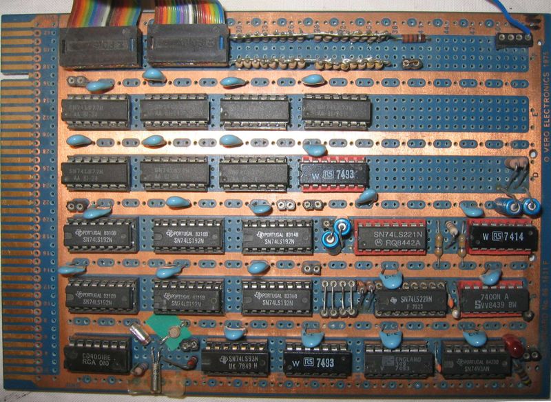
Hobbyist frequency counter circuit built almost entirely of TTL logic chips.
The two states of a wire are usually represented by some measurement of electric current: Voltage is the most common, but current is used in some logic families. A threshold is designed for each logic family. When below that threshold, the wire is "low," when above "high." Digital circuits establish a "no man's area" or "exclusion zone" that is wider than the tolerances of the components. The circuits avoid that area, in order to avoid indeterminate results.
It is usual to allow some tolerance in the voltage levels used; for example, 0 to 2 volts might represent logic 0, and 3 to 5 volts logic 1. A voltage of 2 to 3 volts would be invalid and would occur only in a fault condition or during a logic level transition, as most circuits are not purely resistive, and therefore cannot instantly change voltage levels. However, few logic circuits can detect such a fault, and most will just choose to interpret the signal randomly as either a 0 or a 1.
The levels represent the binary integers or logic levels of 0 and 1. In active-high logic, "low" represents binary 0 and "high" represents binary 1. Active-low logic uses the reverse representation.